Arduino
Heltec Cubecell HTCC AB01 Arduino Guide
Introduction to Guide
Before we begin, please make sure you've followed the steps from this guide, which goes over some initial setup steps.
Objective and Requirements
In this guide, you will learn:
- How to setup your environment
- How to program a basic application that will send packets over the Helium Network
- Verify real-time packets sent to the Helium Console via Hotspot that's in range
For this example, you will need the following:
Hardware
- Heltec CubeCell Board
- Micro USB Type B Cable - Example
Software
Hardware Setup
Adding the Antenna
Your board should have come with a U.FL antenna. All you have to do is attached it to the U.FL port as shown in the image at the top of the guide.
Connect Board
Next, let's connect our board to our computer with a USB 2.0 A-Male to Micro B cable.
Software Setup
Getting the Arduino IDE
Download and install the latest version of Arduino IDE for your preferred OS.
Arduino Board Support
The Heltec CubeCell Board requires one Arduino board support package. Follow the instructions below to install.
CubeCell Dev-boards
To install, open your Arduino IDE:
- Navigate to (File > Preferences), (Arduino > Preferences) on MacOS.
- Find the section at the bottom called Additional Boards Manager URLs:
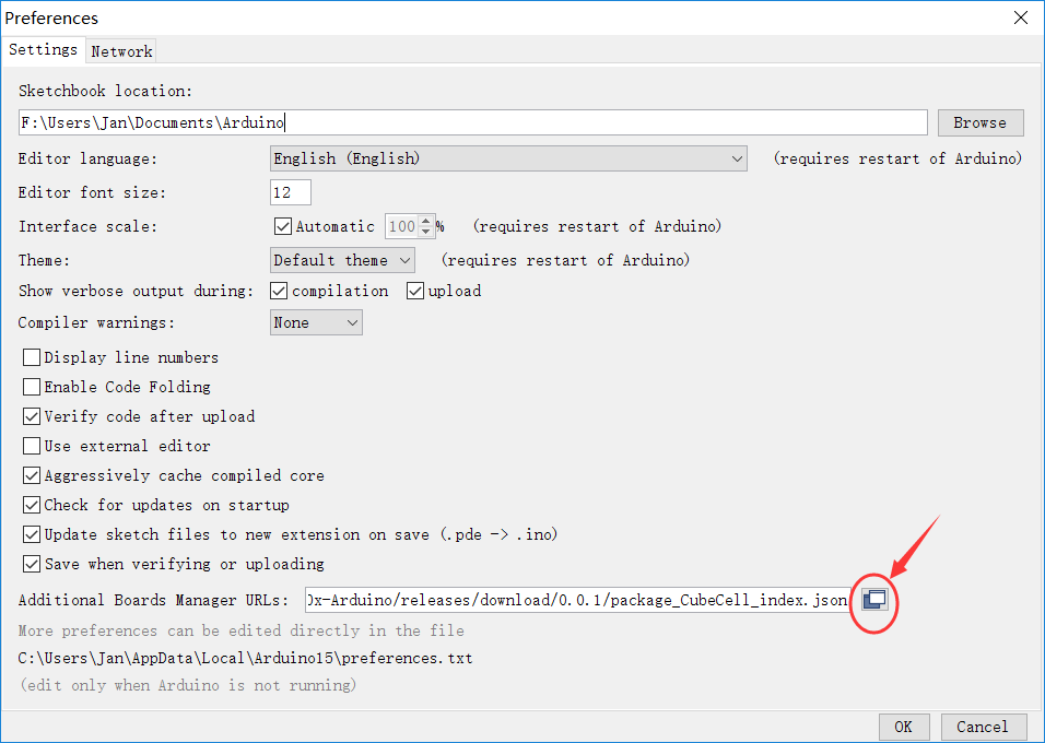
- Add this URL in the text box:
http://resource.heltec.cn/download/package_CubeCell_index.json
- Close the Preferences windows
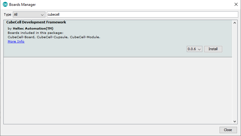
Next, to install this board support package:
- Navigate to (Tools > Boards > Boards Manager...)
- Search for CubeCell Dev-boards
- Select the newest version and click Install
Manual updates to the Heltec runtime libraries
Some versions of Heltec's runtime libraries have set default configuration variables to values that are incompatible with the Helium network, especially when the Heltec device is configured targeting the North American market.
The following discusses two Heltec runtime files that must be inspected to ensure compatibility. The exact location of these files will depend on which operating system you are using, Windows, Linux, or Mac as well as where the Arduino IDE is installed.
The typical top-level locations of the runtime libraries is shown below for each operating system. From there the following discussions will present to you the file locations within these top-level directories/folders. Please note the Heltec library version numbers are expected to change as time goes on.
XXXXX denotes your specfic user id.
Arduino IDE library location
- Windows
C:\Users\XXXX\AppData\Local\Arduino15\packages\CubeCell\hardware\CubeCell\1.0.0
- Linux
/home/XXXXX/.arduino15/packages/CubeCell/hardware/CubeCell/1.0.0
- Mac
/Users/XXXXX/Library/Arduino15/packages/CubeCell/hardware/CubeCell/1.0.0
Verify LoRaWAN Data Rate
Within an editor of your choice open the file path formed by prepending the above described platform specific top level directory structure to the following file:
libraries/LoRa/src/LoRaWan_APP.cpp    (Linux/Mac)
libraries\LoRa\src\LoRaWan_APP.cpp     (Windows)
Within this file look for
#define defaultDrForNoAdr
Depending on the version of the Heltec runtime that is installed this default may be set to DR_0, DR_3, DR_5 or some other value. Note: DR_5 is not valid for US915, the North American market.
The defaultDrForNoAdr setting is tied directly to the maximum size of the data packet you are transferring.
NOTE: If you try to transfer a packet that is larger than this setting allows, your device may successfully join the network but the data transmitted will fail silently.
| Data Rate (DR) | Max Application Payload |
|---|---|
| DR_0 | 11 bytes |
| DR_1 | 53 bytes |
| DR_2 | 125 bytes |
| DR_3 | 242 bytes |
| DR_4 | 242 bytes |
| DR_5 - 7 | Not Valid |
Update the defaultDrForNoAdr as appropriate for your application needs.
The above values are valid for the US902-928MHz region(North America), the values may differ for other LoRa regions, which you can find here.
Dynamic Data Rate Change
If your application needs to change the current uplink data rate dynamically and Adaptive Data Rate (ADR) is not enabled, one can call the
LoRaWAN.setDataRateForNoADR(int8_t dataRate)
API within your sketch. If you do call this API it must be called after the LoRaWAN.init() within your sketch for the change to be effective.
LoRaWAN preamble size
There are some versions of the Heltec runtime libraries that may set a LoRaWAN preamble size that is incompatible with the current LoRaWan specification. If the preamble size is not set correctly your device cannot join the network.
This should be verified in the region-specific file corresponding to the region your device is targeting. Be sure to prepend the above described platform-specific top-level directory structure.
The following is the file that must be checked if targeting region US915. Within an editor of your choice open the file path formed by prepending the above described platform-specific top-level directory structure to the following file:
cores/asr650x/loramac/mac/region/RegionUS915.c     (Linux/Mac)
cores\asr650x\loramac\mac\region\RegionUS915.c     (Windows)
Within this file locate the line below, the 7th parameter which might be 14 should be changed to either 8 or 16. Either value will work. Earlier versions of the runtime may have this value set to 14 which is "not" correct.
Change:
Radio.SetTxConfig( MODsEM_LORA, phyTxPower, 0, bandwidth, phyDr, 1, 14, false, true, 0, 0, false, 3e3 );
To:
Radio.SetTxConfig( MODEM_LORA, phyTxPower, 0, bandwidth, phyDr, 1, 8, false, true, 0, 0, false, 3e3 );
Heltec support has been notified of these issues. Hopefully, a future release of those libs will resolve the issues.
Install Serial Driver
Find Directions on Heltec's website here.
Set Project Configuration Options
The following options are set via the Arduino IDE Tools menu:
Select Board
If you are using the HTCC-AB02 flavor of Heltec board
- Select Tools -> Board: ->CubeCell-Board (HTCC-AB02)
If you are using the HTCC-AB02S GPS-enabled flavor of Heltec board
- Select Tools -> Board: ->CubeCell-GPS (HTCC-AB02S)
Select LoraWAN Configuration Options
Arduino IDE: Until you are familiar with their configuration behavior it is recommended you set the board options as follows:
- Select Tools -> LORAWAN_REGION: -> REGION_US915
- Select Tools -> LORAWAN_CLASS: -> CLASS_A
- Select Tools -> LORAWAN_NETMODE: -> OTTA
- Select Tools -> LORAWAN_ADR: -> OFF
- Select Tools -> LORAWAN_UPLINKMODE: -> UNCONFIRMED
- Select Tools -> LORAWAN_Net_Reservation: -> OFF
- Select Tools -> LORAWAN_AT_SUPPORT: -> OFF
- Select Tools -> LORAWAN_AT_RGB : -> ACTIVE
- Select Tools -> LoRaWan_ Debug Level : -> FREQ&&DIO (for most verbose messages)
Programming Example Sketch
Now that we have the required Arduino board support and library installed, lets program the board with the provided example sketch.
To create a new Arduino sketch, open your Arduino IDE, (File > New). Next, replace the template sketch with the sketch found here, copy and paste the entirety of it.
Next we'll need to fill in the AppEUI(msb), DevEUI(msb), and AppKey(msb), in the sketch, which you can find on the device details page on Console. Be sure to use the formatting buttons to match the endianess and formatting required for the sketch, shown below.
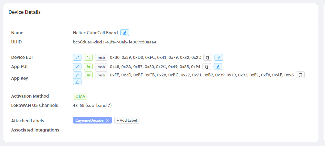
)
At the top of the sketch, replace the three FILL_ME_IN fields, with the matching field from Console, example shown below.

Upload Sketch
We're finally ready to upload our sketch to the board. In the Arduino IDE, click the right arrow button, or navigate to (Sketch > Upload), to build and upload your new firmware to the board. You should see something similar to the image below at the bottom of your Arduino IDE, when the upload is successful.
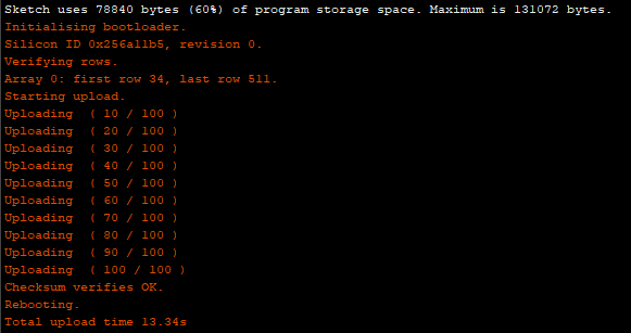
)
Using HTCC-AB02S Board With GPS Capable Sketch
If you are using the HTCC-AB02S board with a sketch that is GPS enabled but find the device is unable to obtain a GPS lock you can try changing the GPS data satellite source via the GPS class Air530.setMode() API. Add the Air530.setmode() to the setup() method of your sketch.
// MODE_GPS - US,
// MODE_GPS_BEIDOU - Chinese - This is the default
// MODE_GPS_GLONASS - Russian
// set what works best for your connectivity, for example:
Air530.setmode(MODE_GPS);
Patching ADR Functionality
The CubeCell may have issues joining the network with ADR OFF. If you're using ADR ON, you may also encounter an issue where your CubeCell stops successfully sending packets after a few minutes. This is caused by the CubeCell firmware's ADR behavior, and may happen if your payload is above the DR0 maximum size (11 bytes).
To patch the CubeCell firmware, find and open the RegionUS915.c file in the firmware directory. On
macOS, an example path would be
~/Library/Arduino15/packages/CubeCell/hardware/CubeCell/1.0.0/cores/asr650x/loramac/mac/region/RegionUS915.c.
Find the following lines in the file and comment them out:
// Decrease the datarate
getPhy.Attribute = PHY_NEXT_LOWER_TX_DR;
getPhy.Datarate = datarate;
getPhy.UplinkDwellTime = adrNext->UplinkDwellTime;
phyParam = RegionUS915GetPhyParam(&getPhy);
datarate = phyParam.Value;
This will prevent the CubeCell from reducing the Data Rate over time and allow you to send larger packets on a repeated, prolonged basis.
Viewing Serial Output
When your firmware update completes, the board will reset, and begin by joining the network. Let's use the Serial Monitor in the Arduino IDE to view the output from the board. We first need to select the serial port again, but this time it will be a different port than the one we selected to communicate with the bootloader. Once again, navigate to (Tools > Port: COM#/ttyACM#), but make sure the serial device, either COM# or ttyACM#, is different! Next navigate to (Tools > Serial Monitor), you should begin to see output similar to below.
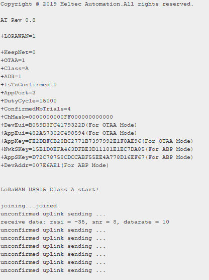
)
Now let's head back to Helium Console and look at our device page, you should see something similar to the screenshot below.
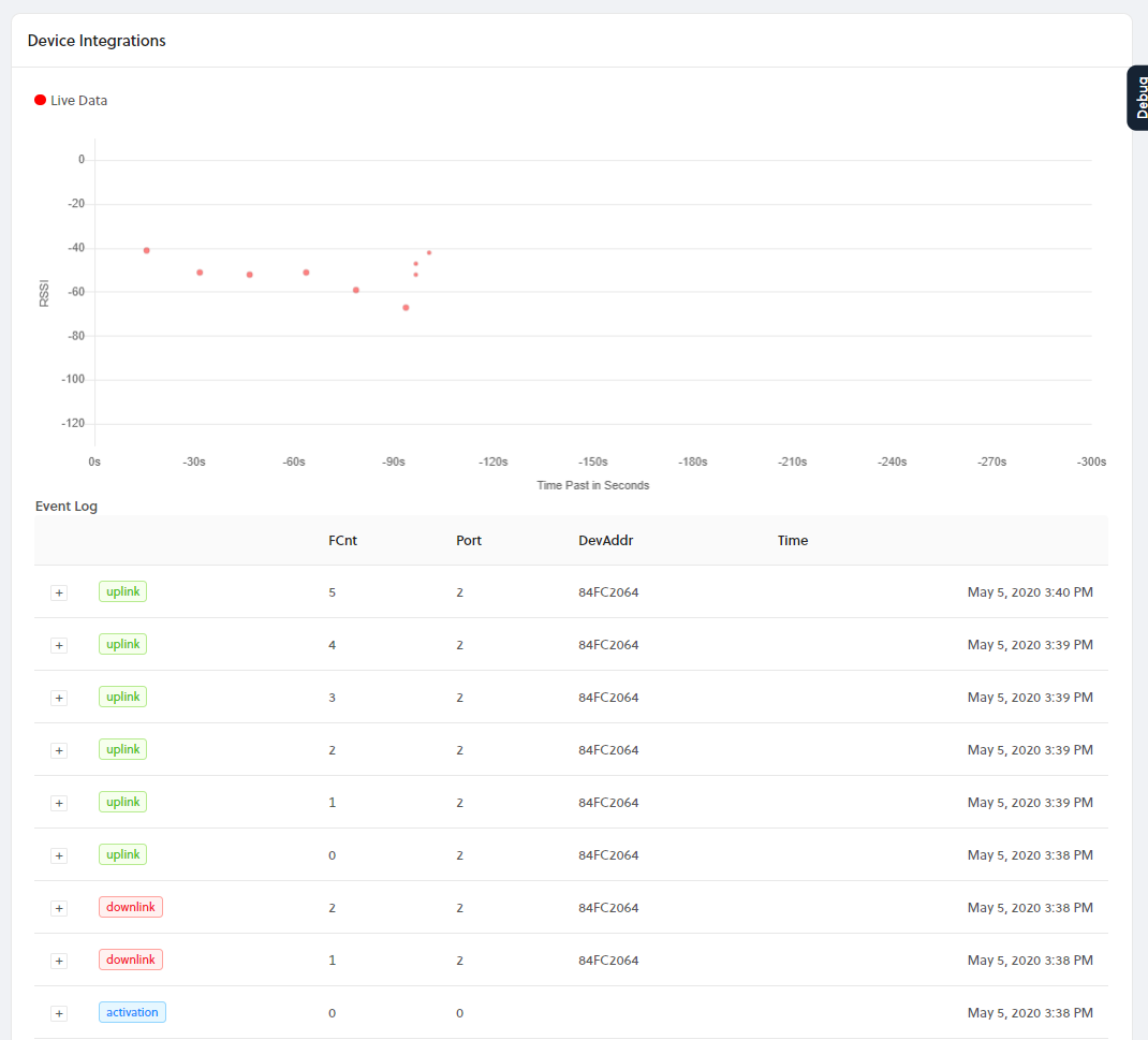
Congratulations! You have just transmitted data on the Helium network! The next step is to learn how to use your device data to build applications, visit our Integrations docs here.