Arduino
LoRa Vision Shield with the Arduino Portenta
Introduction to Guide
Before we begin, please make sure you've followed the steps from the Console quickstart here.
Note: Arduino or MBED experts can skip all the following beginner setup steps, Install the MKRWAN
library, run MKRWANFWUpdate_standalone view the serial monitor to update the LoRa module and go
directly to the step
portenta-lorawan-base64-encoded-sketch.
Objective and Requirements
In this version 0.2.1 of this guide, you will learn:
- How to setup your environment
- How to program a basic application that will send packets over the Helium Network
- Verify real-time packets sent to the Helium Console via Hotspot that's in range
- Setup a full Adafruit.io https connection with a base64 decoder. (Note: CayenneLPP with Adafruit.io is easier to setup but less flexible)
Video Guides
For this example, you will need the following: Power users can jump ahead to the title Arduino Library #1 MKRWAN
Hardware
- Portenta H7
- LoRa Vision Shield
- Micro USB Type C Cable - Example
- U.FL connector for your region. This example will use the US915MHz Antenna Example: U.FL IPEX to SMA Connector Antenna 915MHz for Lora Board
Software
- Arduino software (IDE) Old stable version ~Arduino IDE 1.8.19 or new version ~2.0.0RC3
- Helium Console
Hardware Setup
This step will cover adding an antenna to the LoRa Vision Shield.
Adding the Antenna
The uFL connector is just a push fit on the LoRa board, not the main Portenta board (That uFL connector is for WiFi and BLE). Try not to have to remove and replace the antenna very often. The uFL connectors are rated for 30 connection cycles, so be careful when connecting/disconnecting to not rip the pads off the PCB.
Software Setup
Getting the Arduino IDE
Download and install the latest version of Arduino IDE for your preferred OS.
Arduino Board Support
The PortentaH7 requires one Arduino board support package. Follow the instructions below to install it.
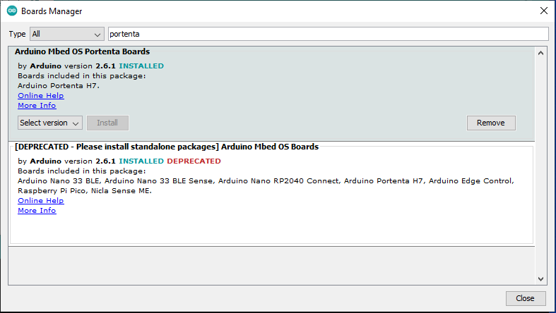
Arduino Mbed OS Portenta Boards
To install, open your Arduino IDE:
- Navigate to (Tools > Boards > Boards Manager...)
- Search for Arduino Mbed OS Portenta Boards
- Select the newest version and click Install
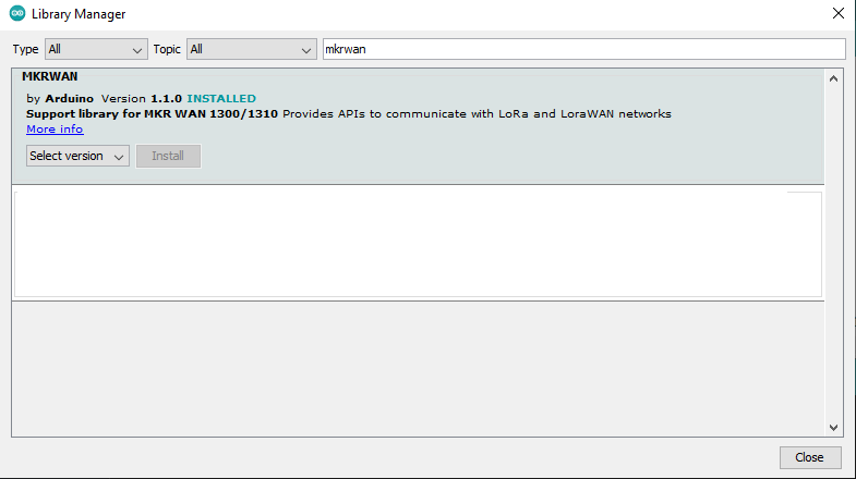
Arduino Library #1 MKRWAN
To communicate with Helium's LoRaWAN network, we'll need to install an Arduino library.
To install, open your Arduino IDE:
- Navigate to Library Manager (Sketch > Include Library > Manage Libraries).
- In the search box, type MKRWAN into the search, select the MKRWAN library latest version, see image below, and click install.
If you prefer to install the zipped latest file from the github click MKRWAN download the zipped file then find the library menu item to install zipped libraries.
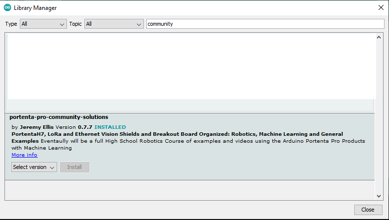
Arduino Library #2 "Portenta Pro Community Solutions"
This is optional as the sketch is provided below
To communicate with Helium's LoRaWAN network, we'll need to install an Arduino library.
To install, open your Arduino IDE:
- Navigate to Library Manager (Sketch > Include Library > Manage Libraries).
- In the search box, type community into the search, select the portenta-pro-community-solutions library latest version see image below, and click Install.
If you prefer to install the zipped latest file from the github click portenta-pro-community-solutions download the zipped file then find the library menu item to install zipped libraries.
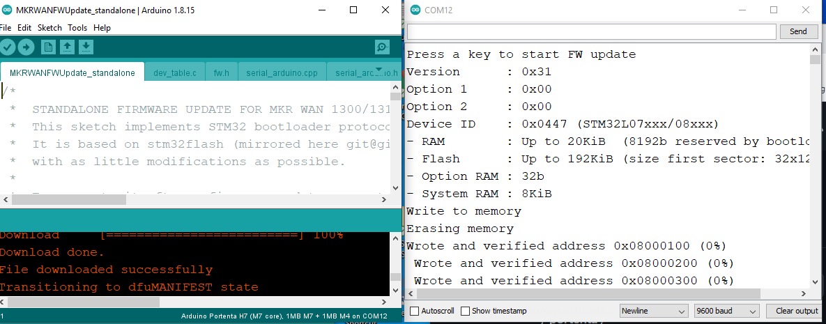
MKRWAN reprogram LoRa board using the MKRWAN example sketch
MKRWANFWUpdate_standalone make sure you run the serial monitor to fully update the LoRa module with the correct program.
The Sketch Install!
Upload Sketch
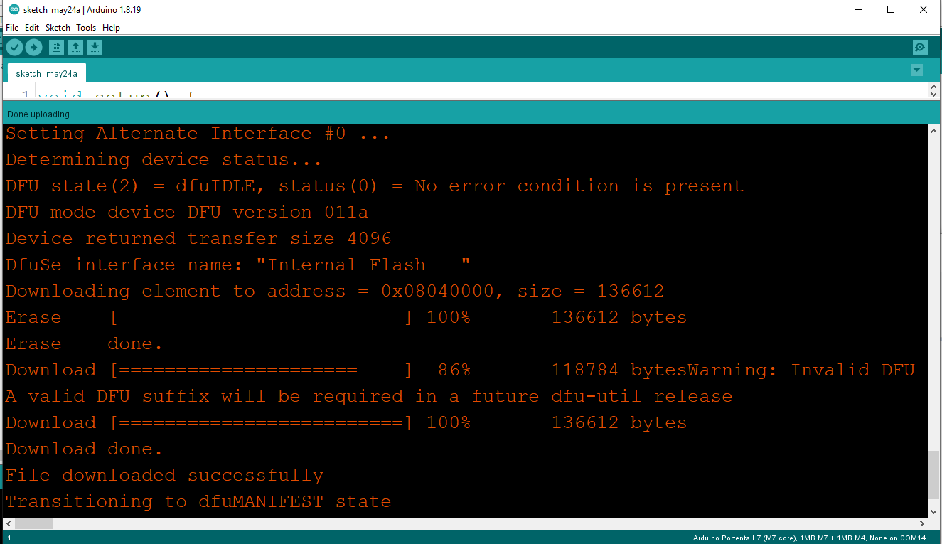
We're finally ready to upload our sketch to the board. In the Arduino IDE, click the right arrow button, or navigate to (Sketch > Upload), to build and upload your new firmware to the board. You should see something similar to the image below at the bottom of your Arduino IDE, when the upload is successful.
Viewing Serial Output
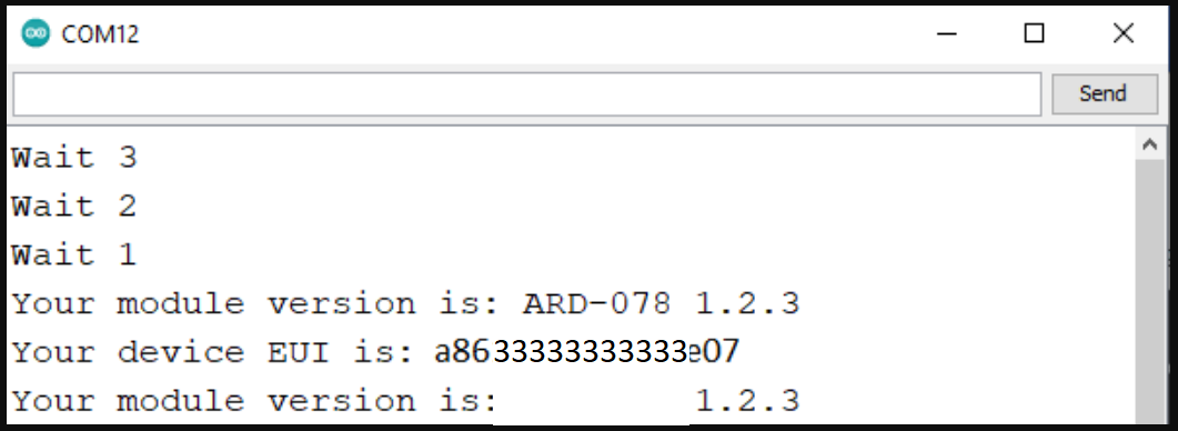
When your firmware update completes, the board will reset, and begin by joining the network. Let's use the Serial Monitor in the Arduino IDE to view the output from the board. We first need to select the serial port again, but this time it will be a different port than the one we selected to communicate with the bootloader. Once again, navigate to (Tools > Port: Arduino Portenta), but make sure the serial device, either COM# or ttyACM#, is different! Next navigate to (Tools > Serial Monitor), you should begin to see output similar to below.
Selecting Board
If you had trouble with the above steps here is an Arduino refresher.
Next, we need to select the correct board to build for in the Arduino IDE. Navigate to (Select Tools > Board: > Arduino Mbed OS Portenta Boards > Arduino PortentaH7 (M7 Core) ).
Enter Bootloader Mode
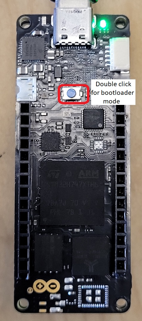
Next, we need to place the board into bootloader mode, which allows us to update it with new firmware. To do this, first plug the device into your computer, make sure the board is getting power (you should see a green LED on). Next, quickly double-click the reset push button on the top side of the board, you should see the green LED slowly pulse about one green pulse per second, showing that you have successfully entered bootloader mode.
Selecting Port
We're almost ready to upload our sketch, the very last step is to select the correct Serial port in the Arduino IDE. Navigate to (Tools > Port: Arduino Portenta). You will also see either COM# or /dev/ttyACM# depending on whether you are on Windows, Mac, or Linux. If you do not see a port, you will need to check if the Arduino drivers have been installed.
Programming Example Sketch
Now that we have the required Arduino board support and library installed, lets program the board with the provided example sketch.
To create a new Arduino sketch, open your Arduino IDE, (File > New). Next, replace the template sketch with the sketch found here, copy and paste the entirety of it or if you have the Portenta-pro-community-solutions library just find example dot334-proof-us915-helium-connect,
Here is the full sketch from the link here,
Portenta LoRaWan Base64 Encoded Sketch
/*
  Helium Send And Receive

   For Adafruit non-CayeenLPP connections for simple sensor Base 64 encoded

  In Helium "functions" section  use this decoder

 function Decoder(bytes, port, uplink_info) {
  var decoded={};
  try{
  var result = String.fromCharCode.apply(null, bytes);
  decoded.value = result;
  return decoded;
  } catch (err) {
  return 'Decoder: ' + err.name + " : " + err.message;;
  }
 }

 And in the integration section of helium use this JSON

 { "value": {{decoded.payload.value}} }


  This sketch demonstrates how to send and receive data with the MKR WAN 1300/1310 LoRa module.
  This example code is in the public domain.
  note: Helium must be setup for what it does with the data
*/

#include <Arduino.h> // Only needed by https://platformio.org/
#include <MKRWAN.h>


LoRaModem modem;
bool connected = false;
bool myWaitForDownlink = false;
bool myDownLink = false;

unsigned long myStoredMillisA;
unsigned long myStoredMillisB;
const unsigned long myTimerDurationA = 30000;  // delay between sending data
const unsigned long myTimerDurationB = 5000;   // delay to wait for a downlink


// Please enter your sensitive data in the Secret tab or arduino_secrets.h
// Note: Best to have the App_Device hard coded. Run the program once to see the value.
//#include "arduino_secrets.h"
#define SECRET_APP_EUI "00000000000000000"
#define SECRET_APP_KEY "00000000000000000000000000000000"


String appEui = SECRET_APP_EUI;   // just strings of the above
String appKey = SECRET_APP_KEY;


void setup() {
  // put your setup code here, to run once:
  Serial.begin(115200);
  pinMode(LEDR,OUTPUT);
  pinMode(LEDG,OUTPUT);
  pinMode(LEDB,OUTPUT);
  digitalWrite(LEDR, HIGH); // new boards HIGH = off
  digitalWrite(LEDG, LOW);
  digitalWrite(LEDB, HIGH);

  //while (!Serial);       // don't wait for serial

  Serial.println("Wait 4");
  delay(3000);             // delay instead, so it works when disconnected
  digitalWrite(LEDG, HIGH);// allows time to connect serial monitor

  Serial.println("Wait 3");
  delay(3000);
  digitalWrite(LEDG, LOW);

  Serial.println("Wait 2");
  delay(3000);
  digitalWrite(LEDG, HIGH);

  Serial.println("Wait 1");
  delay(3000);
  digitalWrite(LEDG, LOW);


  // change this to your regional band (eg. US915, AS923, ...)
  if (!modem.begin(US915)) {
    Serial.println("Failed to start module");
    while (1) {}
  };

  Serial.print("Your module version is: ");
  Serial.println(modem.version());
  Serial.print("Your device EUI is: ");
  Serial.println(modem.deviceEUI());

  Serial.println("Now Disabling all channels and enable channel 1 only for Helium ");

  modem.disableChannel(0);
  modem.enableChannel(1);    // only one enabled for Helium
  modem.disableChannel(2);
  modem.disableChannel(3);
  modem.disableChannel(4);
  modem.disableChannel(5);
  modem.disableChannel(6);
  delay(5000);
  Serial.println("Now Joining the Helium Network ");

}

void loop() {

  while (!connected) {
    Serial.println("trying to reconnect");
    digitalWrite(LEDR, HIGH); // new boards HIGH = off
    digitalWrite(LEDG, LOW);
    digitalWrite(LEDB, LOW);
    connected = modem.joinOTAA(appEui, appKey);
    delay(5000);
    digitalWrite(LEDR, HIGH); // new boards HIGH = off
    digitalWrite(LEDG, LOW);
    digitalWrite(LEDB, HIGH);
    delay(1000);
  }

   if (myWaitForDownlink){

      char rcv[64];
      int i = 0;
      while (modem.available()) {
        rcv[i++] = (char)modem.read();
        myDownLink = true;
      }

       if (millis() - myStoredMillisB >= myTimerDurationB){  // Test whether the period has elapsed
         myStoredMillisB = millis();
         if (!modem.available()) {
             Serial.println("No downlink message received at this time.");
             myWaitForDownlink = false;
         }
      }


      if (myDownLink) {
        myWaitForDownlink = false;
        myDownLink = false;
        Serial.print("Received: ");
        Serial.write(rcv, i);
       // for (unsigned int j = 0; j < i; j++) {
       //   Serial.print(rcv[j] >> 4, HEX);
       //   Serial.print(rcv[j] & 0xF, HEX);
       //   Serial.print(" ");
       // }
        Serial.println();
        digitalWrite(LEDR, LOW); // new boards HIGH = off
        digitalWrite(LEDG, HIGH);
        digitalWrite(LEDB, LOW);

      }

    }


  if (millis() - myStoredMillisA >= myTimerDurationA){  // Test whether the period has elapsed
    myStoredMillisA = millis();                         // IMPORTANT to save the next stored time


  String msg = String(analogRead(A0));   // program expecting numbers!

  Serial.println();
  Serial.print("Sending: " + msg + " - ");
  for (unsigned int i = 0; i < msg.length(); i++) {
    Serial.print(msg[i] >> 4, HEX);
    Serial.print(msg[i] & 0xF, HEX);
    Serial.print(" ");
  }
  Serial.println();

  int err;
  modem.beginPacket();
  modem.print(msg);
  err = modem.endPacket(true);
     if (err > 0) {
        Serial.println("Message sent correctly!");
        digitalWrite(LEDR, HIGH); // new boards HIGH = off
        digitalWrite(LEDG, HIGH);
        digitalWrite(LEDB, LOW);
      } else {
        Serial.println("Error sending message :(");
        Serial.println("(you may send a limited amount of messages per minute, depending on the signal strength");
        Serial.println("it may vary from 1 message every couple of seconds to 1 message every minute)");
        digitalWrite(LEDR, LOW); // new boards HIGH = off
        digitalWrite(LEDG, LOW);
        digitalWrite(LEDB, HIGH);
      }
      myStoredMillisB = millis();
      myWaitForDownlink = true;
      //delay(1000);


     // delay(30000);  // delay 30 seconds for testing

  }  // end timerA

}
Compile Sketch and copy the Device EUI
Once the above sketch is compiled and you have checked the port and loaded the Serial monitor you should see your unique Device EUI. Copy this value!
The Helium Console: Device, Function, Integration, Flows
Helium Console to Arduino Sketch
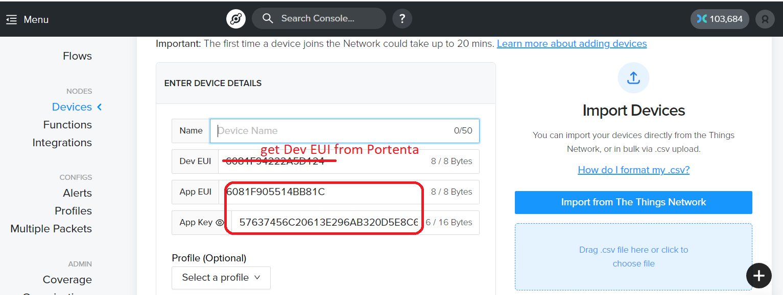
After making a Helium Console login, you we'll need to select a new device "+" and on the Arduino sketch copy into the correct location the SECRET_APP_EUI called the "APP EUI", and the SECRET_APP_KEY which is called the "APP Key", written exactly as you see them on your Helium Console.
#define SECRET_APP_EUI "00000000000000000"
#define SECRET_APP_KEY "00000000000000000000000000000000"
If you are familar with making a #include "arduino_secrets.h" tab then put these values in the
secrets tab which allows you to post your code without showing these values. It does not make your
code more secure so you don't have to do it. Note: If you are confused about the device EUI these
Arduino boards have the deviceEUI fixed per board, so you will have to run the code once, view in
the serial monitor what your boards deviceEUI is and enter that in the Helium Console. (the Helium
console however will randomly give you a deviceEUI (the top one in the list) but you must reset it
with the one specific for your board) See image below
Recompile your Arduino Sketch
The Arduino sketch needs to be recompiled with the new App EUI and APP Key and the Portenta with Vision Shield and LoRa Antenna need to be placed in an advantageous location to find Helium access points. You can power your device with any 5V USB battery pack. Best locations are near windows and the antenna placed vertically.
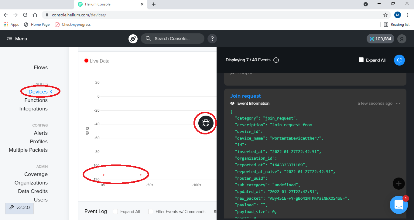
Check Your Helium Device
Now let's head back to the Helium Console and look at our device page, Scroll down to the chart and click the black debug icon to see incoming data, you should see something similar to the screenshot below. First the device needs to "joion" then it can "upload" data.
Congratulations! You have just transmitted data on the Helium network! The next step is to learn how to use your device data to build integrations to view your data, visit the Helium Integrations docs here.
Setting up Adafruit.io
Connect to Adafruit.io
There are a multitude of IOT sites to choose from, each with their own methods to setup. You will be much more confident about those other sites once you have finished setting up a complete HTTPS connection with a decoder. (I will show you the very inefficient base64 decoder simply because LoRaWan naturally base64 encodes your information) Note: See the end of this tutorial for an easier but less flexible Adafruit CayenneLPP MQTT example.
Setup Adafruit.io Feed and Webhook
Get a free Adafruit.io login which allows 5 free feeds (A feed keeps the data sent from a device to Adafruit). Click IO, then feeds, then add a new feed. I call it "led1" but you can call it whatever you like.
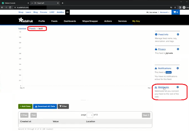
Next create a base (not a fancy) webhook (menu on the right of your feeds, might have to scroll down) and copy the entire webhook URL.
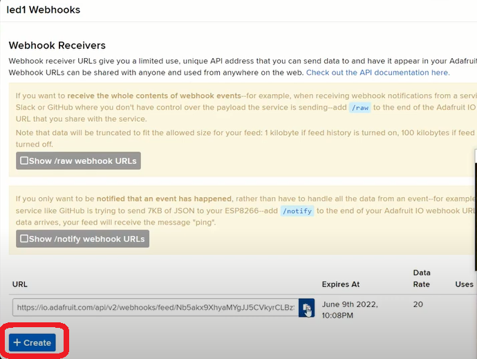
Webhooks are useful since you can define a duration, and they can be used on the web without giving out your main Adafuit KEY, like you would have to if you were using MQTT.
Setup Helium Console Integration for Adafruit http
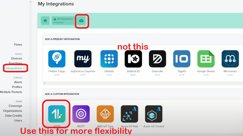
Back at the Helium Console Integrations, make a new integration, give it some sensible name like "adafruit-http-integration" and choose the manual http integration.
You will be entering: 1. A name for the integration, 2. The adafruit Webhook copied earlier 3. Some JSON code to get data from the decoder. This is at the bottom of the page and strangely replaces the code above it.
{ "value": {{decoded.payload.value}} }
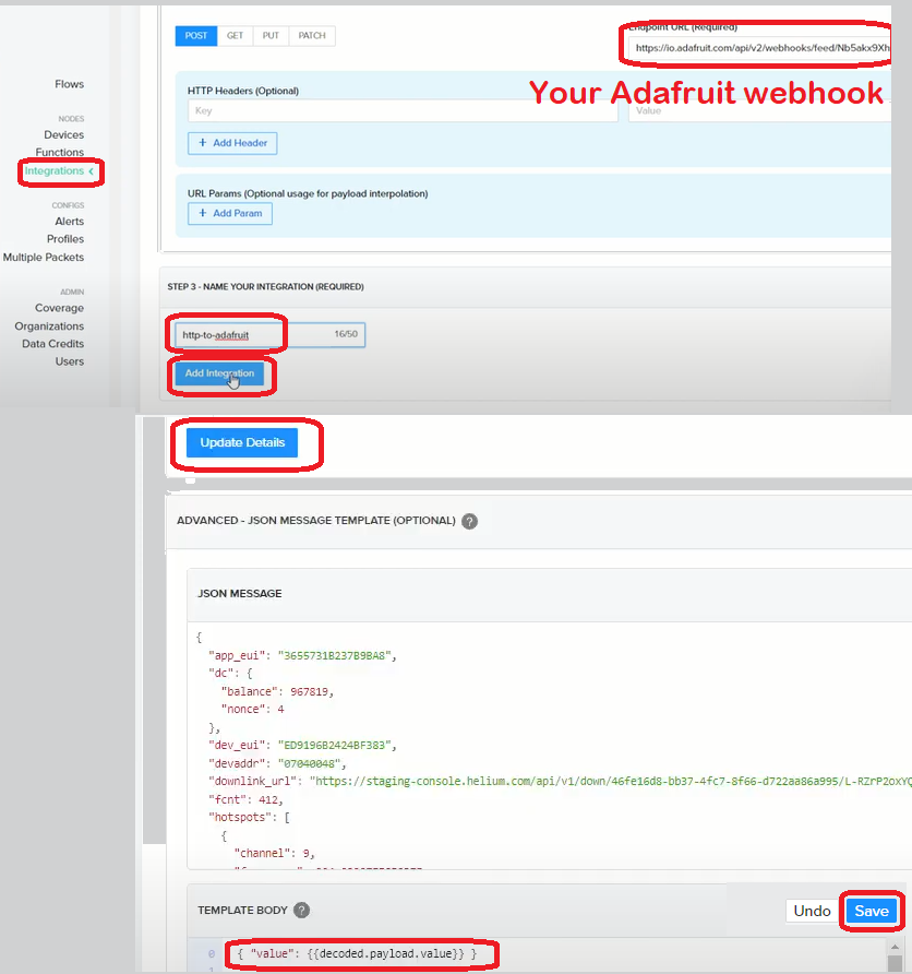
Setup Helium Console Function Decoder
At the Helium Console Functions area. Make a new function give it a sensible name like "Adafruit-http-decoder-function". Then copy this code to replace the barebones decoder
 function Decoder(bytes, port, uplink_info) {
  var decoded={};
  try{
  var result = String.fromCharCode.apply(null, bytes);
  decoded.value = result;
  return decoded;
  } catch (err) {
  return 'Decoder: ' + err.name + " : " + err.message;;
  }
 }

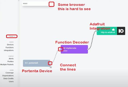
Setup Helium FLOWS to connect the nodes
At the Helium Console go to the FLOWS menu. On some browsers the FLOWS controller is hard to see. Click the "+" and choose and drag onto the screen the Device, Function and Integration you just made. Close the Flows control by re-clicking the hard to see "+"
Connect the 3 icons Portenta Device -to- function decoder -to- adafruit-integration
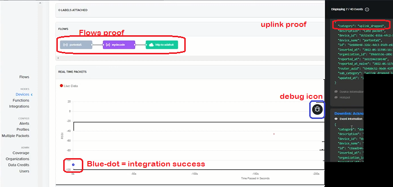
View your blue-dot working device
Now let's head back to Helium Console and look at our device page, Scroll down to the chart and click the black debug icon to see incoming data, you should see something similar to the screenshot below. This time the red-dot should be a blue dot showing a successful Helium Adafruit integration.
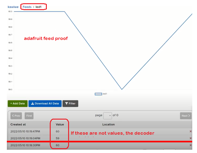
View your Adafruit.io Data
Now go back to Adafruit.io and view your feeds to see if the data is coming in like you are expecting.
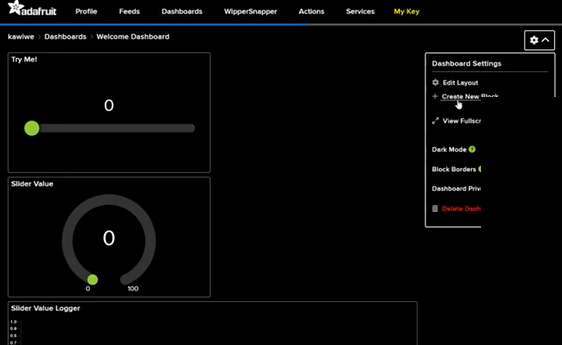
Make an Adafruit.io dashboard
Not as important but fun to go to Adafruit dashboard and click the setup icon top right and create buckets to view your data in streams and graphs etc. Dashboards and feed can be made public if you want to share them with others who have the shareable link.
MQTT Adafruit with CayenneLPP
This is easier but less flexible than the main tutorial
Easier CayenneLPP Adafruit MQTT example
This example is easier than the above but less flexible. The decoder and the feed names are chosen for you and can't be changed. Easy setup can be very useful when you know the negatives.
- When making a new Integration choose the MQTT Adafruit icon
- Enter your username and "my Key" your main adafruit key
- Name the integration and make a new function which will be the default CayenneLPP
- Using FLOWS Connect your Portenta device to the CayenneLPP function and then to the Adafruit MQTT Integration
- Compile the code at dot334 example dot334-us915-helium-mqtt-adafruit-connect.ino which takes an input on the Arduino Portenta A0 pin, converts it to CayenneLPP format, and sends it to Helium.
- Copy the Portenta Device_EUI to Helium and copy the App_EUI and APP_Key to the portenta code then compile again.
- Check the HElium device chart and debug Icon to see when uplink data is flowing, see if the graph dots are blue for successful integration with Adafruit. The results should be the same as above.
CayenneLPP Portenta Example Sketch
Following is the full arduino sketch from the link here
/*
  Helium Send And Receive
  This sketch demonstrates how to send and receive data with the MKR WAN 1300/1310 LoRa module.
  This example code is in the public domain.
  note: Helium must be setup for what it does with the CayenneLPP encoded data
*/

#include <Arduino.h> // Only needed by https://platformio.org/
#include <MKRWAN.h>
#include <CayenneLPP.h>


LoRaModem modem;
CayenneLPP lpp(51);
bool connected = false;
bool myWaitForDownlink = false;
bool myDownLink = false;

unsigned long myStoredMillisA;
unsigned long myStoredMillisB;
const unsigned long myTimerDurationA = 30000;  // delay between sending data
const unsigned long myTimerDurationB = 5000;   // delay to wait for a downlink


// Please enter your sensitive data in the Secret tab or arduino_secrets.h
// Note: Best to have the App_Device hard coded. Run the program once to see the value.
//#include "arduino_secrets.h"
#define SECRET_APP_EUI "0000000000000000"
#define SECRET_APP_KEY "00000000000000000000000000000000"


String appEui = SECRET_APP_EUI;   // just strings of the above
String appKey = SECRET_APP_KEY;


void setup() {
  // put your setup code here, to run once:
  Serial.begin(115200);
  pinMode(LEDR,OUTPUT);
  pinMode(LEDG,OUTPUT);
  pinMode(LEDB,OUTPUT);
  digitalWrite(LEDR, HIGH); // new boards HIGH = off
  digitalWrite(LEDG, LOW);
  digitalWrite(LEDB, HIGH);

  //while (!Serial);       // don't wait for serial

  Serial.println("Wait 4");
  delay(3000);             // delay instead, so it works when disconnected
  digitalWrite(LEDG, HIGH);// allows time to connect serial monitor

  Serial.println("Wait 3");
  delay(3000);
  digitalWrite(LEDG, LOW);

  Serial.println("Wait 2");
  delay(3000);
  digitalWrite(LEDG, HIGH);

  Serial.println("Wait 1");
  delay(3000);
  digitalWrite(LEDG, LOW);


  // change this to your regional band (eg. US915, AS923, ...)
  if (!modem.begin(US915)) {
    Serial.println("Failed to start module");
    while (1) {}
  };

  Serial.print("Your module version is: ");
  Serial.println(modem.version());
  Serial.print("Your device EUI is: ");
  Serial.println(modem.deviceEUI());

  Serial.println("Now Disabling all channels and enable channel 1 only for Helium ");

  modem.disableChannel(0);
  modem.enableChannel(1);    // only one enabled for Helium
  modem.disableChannel(2);
  modem.disableChannel(3);
  modem.disableChannel(4);
  modem.disableChannel(5);
  modem.disableChannel(6);
  delay(5000);
  Serial.println("Now Joining the Helium Network ");

}

void loop() {

  while (!connected) {
    Serial.println("trying to reconnect");
    digitalWrite(LEDR, HIGH); // new boards HIGH = off
    digitalWrite(LEDG, LOW);
    digitalWrite(LEDB, LOW);
    connected = modem.joinOTAA(appEui, appKey);
    delay(5000);
    digitalWrite(LEDR, HIGH); // new boards HIGH = off
    digitalWrite(LEDG, LOW);
    digitalWrite(LEDB, HIGH);
    delay(1000);
  }

   if (myWaitForDownlink){

      char rcv[64];
      int i = 0;
      while (modem.available()) {
        rcv[i++] = (char)modem.read();
        myDownLink = true;
      }

       if (millis() - myStoredMillisB >= myTimerDurationB){  // Test whether the period has elapsed
         myStoredMillisB = millis();
         if (!modem.available()) {
             Serial.println("No downlink message received at this time.");
             myWaitForDownlink = false;
         }
      }


      if (myDownLink) {
        myWaitForDownlink = false;
        myDownLink = false;
        Serial.print("Received: ");
        Serial.write(rcv, i);
       // for (unsigned int j = 0; j < i; j++) {
       //   Serial.print(rcv[j] >> 4, HEX);
       //   Serial.print(rcv[j] & 0xF, HEX);
       //   Serial.print(" ");
       // }
        Serial.println();
        Serial.println();
        digitalWrite(LEDR, LOW); // new boards HIGH = off
        digitalWrite(LEDG, HIGH);
        digitalWrite(LEDB, LOW);

      }

    }


  if (millis() - myStoredMillisA >= myTimerDurationA){  // Test whether the period has elapsed
    myStoredMillisA = millis();                         // IMPORTANT to save the next stored time


      lpp.reset();
      float x = analogRead(A0); //analogRead(A0) or rand() / 10000000.0;
      lpp.addDigitalOutput(1, x);


      /*
      // Can do any of these
      lpp.reset();
      lpp.addDigitalInput(1, 0);
      lpp.addDigitalOutput(2, 1);
      lpp.addAnalogInput(3, 1.23f);
      lpp.addAnalogOutput(4, 3.45f);
      lpp.addLuminosity(5, 20304);
      lpp.addPresence(6, 1);
      lpp.addTemperature(7, 26.5f);
      lpp.addRelativeHumidity(8, 86.6f);
      lpp.addAccelerometer(9, 1.234f, -1.234f, 0.567f);
      lpp.addBarometricPressure(10, 1023.4f);
      lpp.addGyrometer(1, -12.34f, 45.56f, 89.01f);
      lpp.addGPS(1, -12.34f, 45.56f, 9.01f);

      lpp.addUnixTime(1, 135005160);

      lpp.addGenericSensor(1, 4294967295);
      lpp.addVoltage(1, 3.35);
      lpp.addCurrent(1, 0.321);
      lpp.addFrequency(1, 50);
      lpp.addPercentage(1, 100);
      lpp.addAltitude(1 , 50);
      lpp.addPower(1 , 50000);
      lpp.addDistance(1 , 10.555);
      lpp.addEnergy(1 , 19.055);
      lpp.addDirection(1 , 90);
      lpp.addSwitch(1 , 0);

      lpp.addConcentration(1 , 512);
      lpp.addColour(1 , 64, 128, 255);

      */


      Serial.println();
      Serial.println("Sending:" + String(x, 1));


      int err;
      modem.beginPacket();
      modem.write(lpp.getBuffer(), lpp.getSize());
      err = modem.endPacket(true);
      if (err > 0) {
        Serial.println("Message sent correctly!");
        digitalWrite(LEDR, HIGH); // new boards HIGH = off
        digitalWrite(LEDG, HIGH);
        digitalWrite(LEDB, LOW);
      } else {
        Serial.println("Error sending message :(");
        Serial.println("(you may send a limited amount of messages per minute, depending on the signal strength");
        Serial.println("it may vary from 1 message every couple of seconds to 1 message every minute)");
        digitalWrite(LEDR, LOW); // new boards HIGH = off
        digitalWrite(LEDG, LOW);
        digitalWrite(LEDB, HIGH);
      }
      myStoredMillisB = millis();
      myWaitForDownlink = true;
      //delay(1000);


     // delay(30000);  // delay 30 seconds for testing

  }  // end timerA

}
Video Guides
Fails
Fails
What to do when it fails! Lots of possible issues, but your best bet is the Helium console debug and connection graph.
- If you are not getting a red dot your 3 secret numberes (deviceEUI, AppEUI, AppKey) are probably
not correct or you forgot to run the MRKWAN
MKRWANFWUpdate_standalonecode here - If you get a red dot with the debug window only saying "Join Request" but never "uplink" you are probably having network issues, just like WiFi issues if you move around, get closer to a window, get higher, put the device on battery and leave it somewhere with a good view to the nearest Helium gateway, use the Helium explorer to see which direction the nearest gateway is.
- If in the debug pane you see "uplink" but you only have a red dot then you have connected to Helium and that is good, you just have not connected with an integration. Check your decoder and integration settings Adafruit here
- If the dot is yellow you have connected with the function decoder but not yet fully with the integration, check you decoder and integration settings decoder here
- If the dot is blue you have successfully integrated but the data may not be in the correct format, check your decoder/integration Blue dot here
- Hopefully the above helps. It is very difficult to determine if your nearest Helium Gateway is having issues or if you have done something incorrect with your setup. Once you have a device that connects consistently, then other devices are much easier to set up. Good luck.