AdafruitO
Adafruit IO Guide with Adafruit Feather M0 RFM95
Introduction to Guide
Before we begin, please make sure you've followed the steps from the Console quickstart here. This will ensure you have a Console account and have created a new device.
Objective and Requirements
In this guide, you will learn how to:
- Connect your hardware
- Setup your firmware environment
- Program a basic application that will send packets over the Helium Network
- Verify real-time packets sent to the Helium Console via Hotspot that's in range
- Create an AdafruitIO integration and attach to device
For this example, you will need the following:
Hardware
- Adafruit Feather M0 - RFM95
- DHT22 Temperature and Humidity Sensor
- Micro USB Type B Cable - Example
- Jumper cables
Software
Hardware Setup
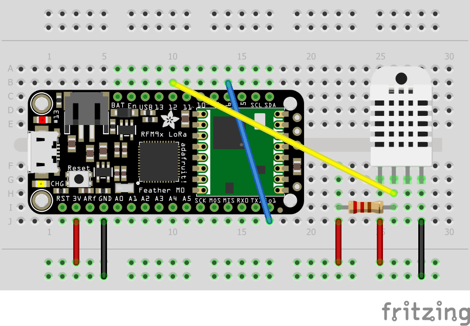
This step will cover adding an antenna, jumping pins on the LoRaWAN radio, and finally wiring the DHT22 temperature and humidity sensor. Below is a breadboard wiring diagram that you can reference for your setup.
Adding the Antenna
Please visit Adafruit's Documentation for antenna options and instructions here.
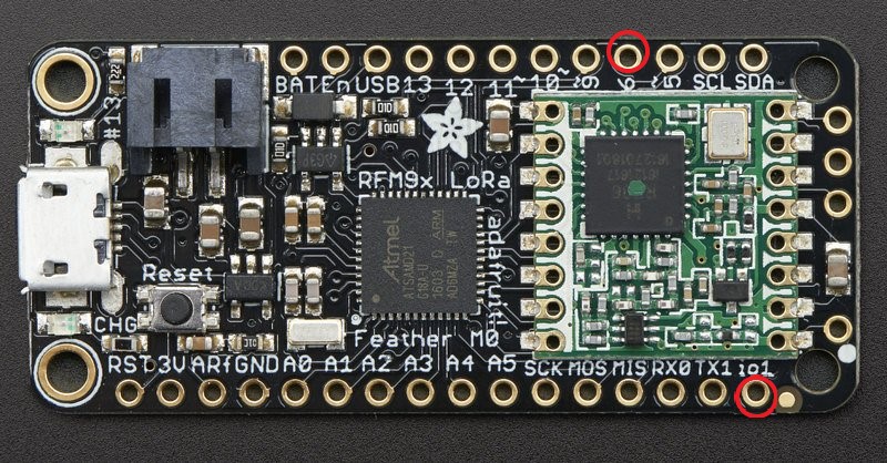
Jumping IO1 to Pin6
In order to use the RFM95 radio module onboard the Feather M0 for LoRaWAN we'll need to connect two
pins together. The pins are labeled io1 and 6 on the board, as shown below. If you have the
headers soldered on, you can use a female to female jumper cable to connect them, or you can simply
solder a wire from pin to pin.
Wiring the DHT22 Sensor
Connect the signal pin 2 of the DHT22 sensor to pin 12 on the feather board. You will also need
to add a pull up resister (20-50k) between the signal pin 2 of the DHT22 sensor and the 3.3V
supply. Last, connect the power(3.3V or 5V) and ground pins. Please reference the breadboard diagram
above.
Software Setup
Getting the Arduino IDE
Download and install the latest version of Arduino IDE for your preferred OS.
Arduino Board Support
The Adafruit Feather M0 requires two Arduino board support packages. Follow the instructions below to install both.
Arduino SAMD Boards (32-bits ARM Cortex-M0+)
To install, open your Arduino IDE:
- Navigate to (Tools > Boards > Boards Manager...)
- Search for Arduino SAMD Boards (32-bits ARM Cortex-M0+)
- Select the newest version and click Install
Adafruit SAMD Boards
To install, open your Arduino IDE:
- Navigate to (File > Preferences), (Arduino > Preferences) on MacOS.
- Find the section at the bottom called Additional Boards Manager URLs:
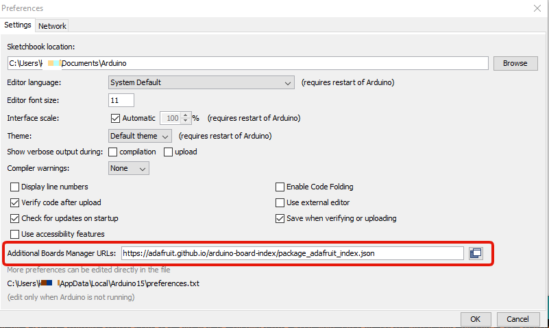
- Add this URL in the text box:
https://adafruit.github.io/arduino-board-index/package_adafruit_index.json
- Close the Preferences windows
Next, to install this board support package:
- Navigate to (Tools > Boards > Boards Manager...)
- Search for Adafruit SAMD Boards
- Select the newest version and click Install
Arduino Library
To communicate with Helium's LoRaWAN network, we'll need to install an Arduino library.
To install, open your Arduino IDE:
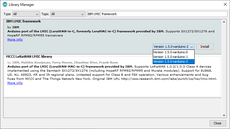
- Navigate to Library Manager (Sketch > Include Library > Manage Libraries).
- In the search box, type IBM LMIC framework into the search, select the version shown below, and click Install.
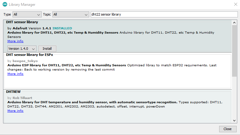
To communicate with the DHT22 sensor, we'll need to install an Arduino library.
To install, open your Arduino IDE:
- Navigate to Library Manager (Sketch > Include Library > Manage Libraries).
- In the search box, type DHT22 sensor library into the search, select the version shown below, and click Install.
To encode our data with CayenneLPP, we'll need to install an Arduino library.
To install, open your Arduino IDE:
- Navigate to Library Manager (Sketch > Include Library > Manage Libraries).
- In the search box, type CayenneLPP into the search, select the version shown below, and click Install.

Update IBM LMIC framework config.h
This library requires that a config file be setup properly. After you have installed the
IBM LMIC framework library, navigate to its directory on your operating system found below. Next,
replace the config.h file in this directory with this
config.h
file.
linux: /home/{user}/Arduino/libraries/IBM_LMIC_framework/src/lmic windows: Documents/Arduino/libraries/IBM_LMIC_framework/src/lmic mac os: Documents/Arduino/libraries/IBM_LMIC_framework/src/lmic
Programming Example Sketch
Now that we have the required Arduino board support and library installed, lets program the board with the provided example sketch.
To create a new Arduino sketch, open your Arduino IDE, (File > New). Next, replace the template sketch with the sketch found here, copy and paste the entirety of it.
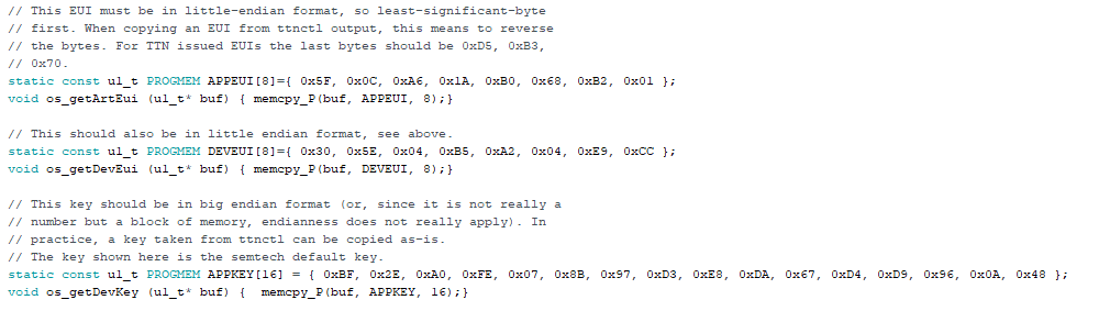
Next we'll need to fill in the AppEUI(lsb), DevEUI(lsb), and AppKey(msb), in the sketch, which you can find on the device details page on Console. Be sure to use the formatting buttons to match the endianness and formatting required for the sketch, shown below.
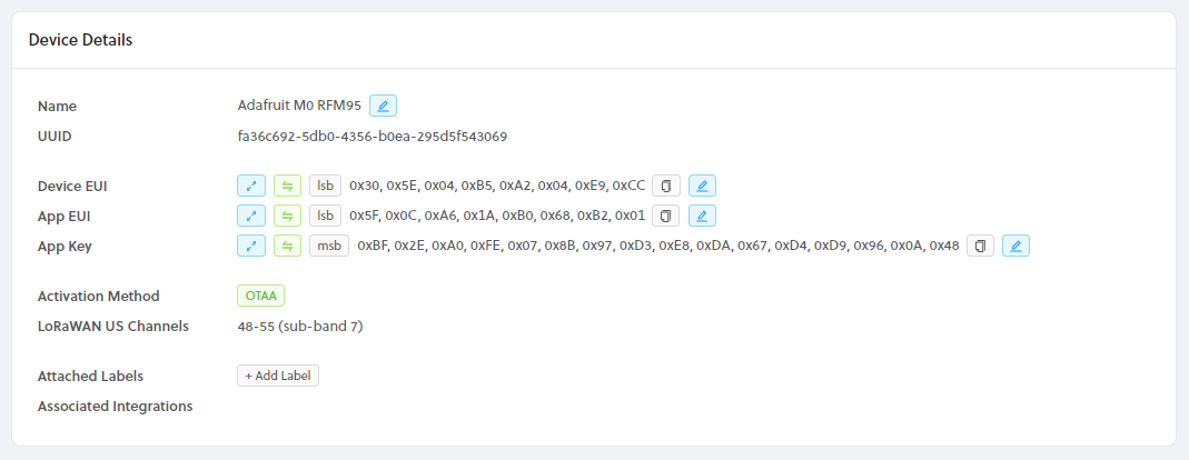
At the top of the sketch, replace the three FILL_ME_IN fields, with the matching field from Console, example shown below.
Selecting Board
Next, we need to select the correct board to build for in the Arduino IDE. Navigate to (Select Tools > Board: > Adafruit Feather M0).
Enter Bootloader Mode
Next, we need to place the board into bootloader mode, which allows us to update it with new firmware. To do this, first plug the device into your computer, make sure the power switch is turned on (you should see a red LED on). Next, quickly double click the reset push button on the top side of the board, you should see the red LED slowly blink. If you see this then you have successfully entered bootloader mode.
Selecting Port
We're almost ready to upload our sketch, the very last step is to select the correct Serial port in the Arduino IDE. Navigate to (Tools > Port: Adafruit Feather M0). You will also see either COM# or /dev/ttyACM# depending on whether you are on Windows, Mac, or Linux. If you do not see a port, please visit the Drivers section in Adafruit's Docs to make sure you have what's needed for your operating system.
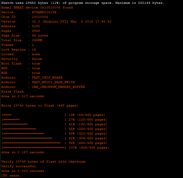
Upload Sketch
We're finally ready to upload our sketch to the board. In the Arduino IDE, click the right arrow button, or navigate to (Sketch > Upload), to build and upload your new firmware to the board. You should see something similar to the image below at the bottom of your Arduino IDE, when the upload is successful.
Viewing Serial Output
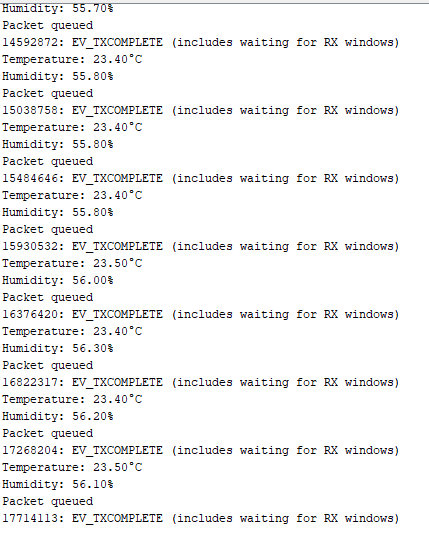
When your firmware update completes, the board will reset, and begin by joining the network. Let's use the Serial Monitor in the Arduino IDE to view the output from the board. We first need to select the serial port again, but this time it will be a different port than the one we selected to communicate with the bootloader. Once again, navigate to (Tools > Port: Adafruit Feather M0), but make sure the serial device, either COM# or ttyACM#, is different! Next navigate to (Tools > Serial Monitor), you should begin to see output similar to below.
Now let's head back to Helium Console and look at our device page, you should see something similar to the screenshot below.
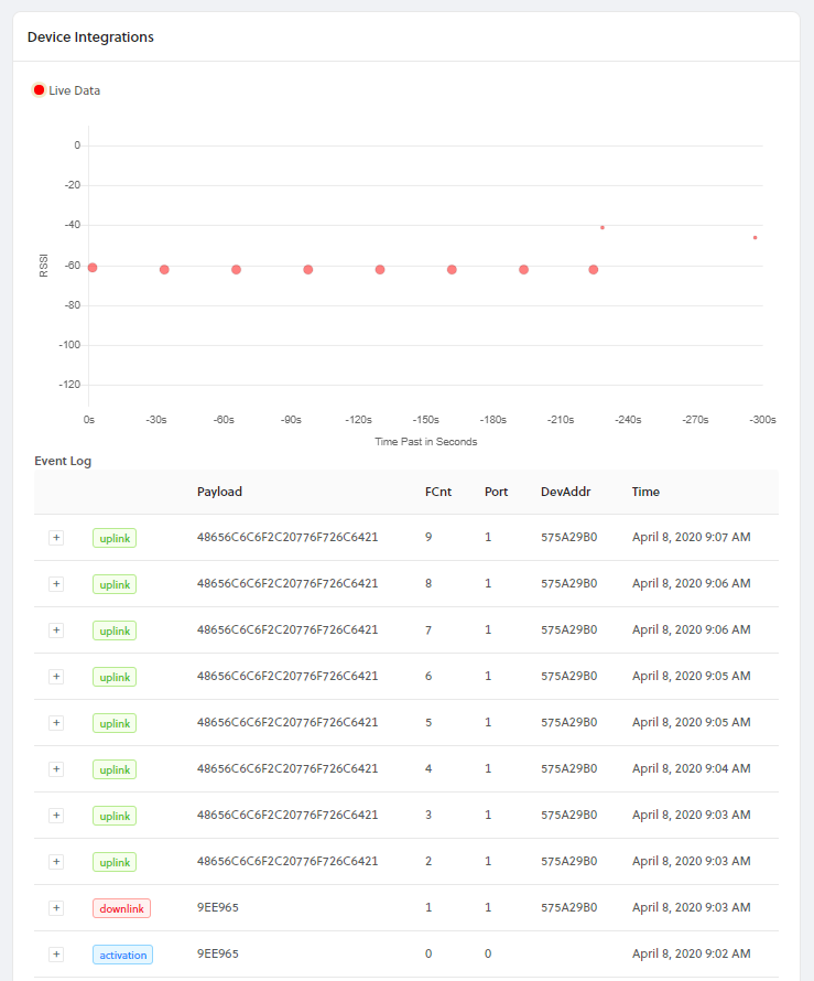
Congratulations! You have just transmitted data on the Helium network! The next step is to create and attach the AdafruitIO integration.
Adafruit IO
Next we'll create and attach the Adafruit IO integration.
You can sign up for a free account at https://io.adafruit.com.
To add the integration in Console, go to Integrations on the left-hand menu. Select the integration to add - in this case, the Adafruit IO integration as shown below.

The next step is to enter your Adafruit IO username and key. These can be found by visiting https://io.adafruit.com and clicking MyKey in the top right corner as shown below.

You will then be presented with both your username and key as shown below.

Copy these values into the username and key fields in Console for the integration configuration shown below.

Last for this step, you can optionally change the group name that is set to {{device_id}} by
default. The group name is used to group one or more data values that is received from a device and
sent to AdafruitIO in a single message. This name is used as the default because it is guaranteed to
be unique for every Helium device. You can use any of the available template tags which are auto
populated when messages are actually sent, which are {{device_id}}, {{device_eui}}, and
{{device_name}}. This integration uses group topics to send device data to AdafruitIO over MQTT,
you can read more about it here.
Next let's name the integration in step 3, you will use this name later to identify the integration when attaching it to devices.

The very last step is to select the decoder that will be used to decode the data payload received from your device. We will be using the CayenneLPP decoder as shown below and encoding the sensor data with CayenneLPP. Last be sure to click Create Integration to finish.

Connecting AdafruitIO Integration to Device
Now that we have our integration created, the last step is to attach the label to our device. To do
this, navigate your device page and click the Add Label button shown below.

Search for the AdafruitIO label, select, and finally click Add Label.

You should now see your data appearing on Adafruit IO under Feeds as shown below.

That completes this guide!